Pore Pressure Build up and Dissipation When Pile Driven in Clay, Essay Example
Pile driving into low permeability soils causes the pile to undergo a process where it, dependent on time, gains capacity. One factor is the pore pressure built up and dissipation after the pile has been driven. This research will focus on these factors affecting driven pile installations in clay strata. The paper analyzes research, as well as models, in order to find out the pore pressure dissipation, capacity gain rates, time, and their effect on the gain capacity of the driven pile. It will also mention the influence clays have on pile driving: from pore pressures developed during driving, to the dissipation of excess pore pressures and the displacement caused by driving. The results of this research will have wide-ranging benefits that could with cost benefits of projects, particularly in seismic foundation projects.
Introduction
Pore Pressure Buildup
Pore Pressure is a term that is used in engineering to describe the build-up of fluid that is trapped. The fluid cannot leave the pores and is trapped at a pressure that is dependent on the density, depth underground and the type of soil. Pore pressure buildup can cause instability and is directly related to how quickly the load is placed; however, over time, the pore pressure will dissipate and the soil will recover its strength. This, of course, depends on the permeability and compressibility factors of the soil itself. The capacity of the pile is usually obtained from a load test and is usually considered to be the long term pile capacity; however, after the driving process is conducted, the soils that surround the pile shaft, as well as underneath the pile tip, are disrupted due to excess pore water pressure build up. The characteristics of the soil are significant to how much pore pressure occurs. The pile capacity can increase as the strength of the soil increases. This is common in soils with low permeability such as clay. (Chen et al.) In addition, one of the major factors before pile driving is to therefore determine how much pore pressure builds up will occur. There have been programs developed, known as limit equilibrium stability programs, which determine the pore pressure and the amount of toleration. This type of program allows the geotechnical engineer to input pore pressure values and then analyze the stability. (WSDOT, 2010)
Efforts in the geotechnical field have been underway in order to quantify the time for pile capacity and the methods for pile design from capacity gain in order to obtain a better understanding and predict the compression and excess porewater pressure that occurs from piles. Driving of piles can result in the buildup of excess porewater pressure (Figure 1). In addition, the excess porewater pressure combined with the sensitivity of clay can result in the soil losing its shear strength; however, the porewater pressure dissipates over time and then the soil consolidates and increases in strength, greater than its initial strength. This causes the soil to “freeze” with the dissipation of the porewater pressure. The “freeze” and gain is capacity is dependent on the mechanisms of stress from the dissipation of pore pressure that are built up during the stress mechanism. In addition, the disturbance of clay from the driven pile and expansion from the pressure causes the expansion. (Swan)
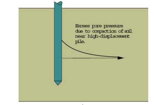
Figure 1. Buildup of Excess pore pressure. (Swan)
One major factor contributes to the process of capacity gain in pile driven clay strata and will be the focus of this paper. The factor is the pore pressure build up and dissipation after the pile has been driven. The following paper examines literature that focuses on the effect of piles driven in clay on capacity gain. In addition, the paper evaluates the benefits of the research in terms of cost saving. For instance, areas such as California have put great effort into seismic response of pile foundations and the effects of pile foundations in clays for both determined the essential properties for seismic design along with cost. First, this paper will provide an overview of pile foundations and pile driving.
Pile Foundations
Pile foundations are the piece of a structure that is used to manipulate the load of a structure to the ground at a specific point below the ground surface. There are two main components to the pile foundation: pile cap and piles. The piles are the pieces that transfer the load to the deeper part of the soil or rock. In addition, the piles have a high bearing capacity; therefore, they are used for the deeper soil since shallow soil has a low bearing capacity. There are different types of material that is used for piles such as wood, concrete and steel. Piles made from these types of materials are usually driven into the ground. It is the type of soil that is used which results in the characteristics of the load transmitting of the piles. Pile foundations are used if investigations of a site illustrate that the soil is too weak and unstable. In addition, in most cases, pile foundations are more costly efficient that ground improvement. (Abebe and Smith)
Piles Driven in Clay Strata
Soils have different responses to the pile loads and are classified as granular or clays. Granular soils are non-cohesive and clays or cohesive. Piles strength is dependent of different factors, including the soil type. The shaft capacity of piles driven into clay has been an important issue in geotechnical engineering. One of the important issues is the amount of stress around the pile. There has been numerous instruments developed in order to measure for the created stress; however, it is unknown how the stresses are affected by the driven piles. (Randolph et al., 1979) As a pile is driven in soil, it displaces the soil. The soil is displaced mostly radially with some vertical displacement along the shaft and beneath the toe (Komurka and Wager, 2003). In clay, it has been found that pile driving can alter the stress of the soil significantly at up to 20 pile radii. (Randolph et al., 1979) In fact, Yang (1970) has further indicated that clay can remold the soil at around ½ pile diameter and at a distance of around 1.5 pile diameters. Research is currently investigating other factors affecting piles driven into clay strata. For this paper, a research review is focused on pore pressure build up and dissipation of piles driven in clay.
Piles that are driven in clay obtain their capacity from friction. These types of piles are mostly used underneath footings or in large clusters underneath mats or rafts. The bearing capacity of piles used in large clusters is equal to the amount of piles multiplied by the bearing capacity per pile. However, in some cases the pile cluster might be smaller than the number of piles times the bearing capacity due to block failure. Block failure can be avoided if the pile spacing is equal or greater than three of the pile diameters. In addition to the types of piles used, settlement of the loads is a factor in the type of design of the piles used in clay. As mentioned previously, there is no specific relationship between the characteristics of one pile and a group of piles. The relationship is dependent on the size and the type and sequence of soil strata. (FM 5-134) In addition, for piles driven in clay, pore pressure buildup and dissipation, is a factor that contributes to capacity gain.
Literature Review
In a research paper written by Carter (et al., 1979), stress and pore pressure changes due to cavity expansion in clay were investigated. Clay parameters were chosen in order to create a simulation of a homogenous deposit of clay. The type of clay used was Boston Blue clay. The authors first explain the need to chart the dissipation of pore pressure during and after the cavity expansion. The authors indicate that a consolidation analysis is most useful. First the authors describe the consolidation analysis using non-clay soil and under the assumption that the conditions were of plane strain and axial symmetry, which leads to a one-dimensional formula. The formula that is used when stress is combined with movement of pore fluid through a saturated soil is written as the following:
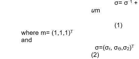
The second formula is the total stress components and is also referred to as the stress principle. (Carter et al., 1979) Although this formula presents the amount of stress, it does not account for pore pressure or other types of material used, such as clay. In order to alleviate these types of issues, models were developed to create an expansion of a cavity. The authors therefore created calculations for the expansion of the cavity using an initial radius of zero, a fast deformation rate. Calculations were performed for the expansion of a cavity of initial radius fast deformation rate. The results of their calculation illustrated the variation with the cavity size and the total pressure and pore pressure as well. The results from this study also showed that the limit pressure is reached before the cavity doubles in size. In addition, it was indicated that the process of expanding the cavity significantly changed the stress at the cavity interface. Furthermore, after the cavity size doubled in size, it was found to stay constant as the pore pressure dissipated concurrent with the pore fluid. In order to confirm the validity of their model, Carter (et al., 1979) used a Cambridge self-boring pressure meter in the field with the same results.
Chen (et al.) conducted a field research project to illustrate the effect of time on pile capacity when driven in clay. Two different piles were used, soft marine clay deposit and silty sand deposit. Static pile load tests were performed during the first week of pile driving and 2-3 weeks after the pile driving. In the clay pile, the volume of clay it was predicted that the volume that would be displaced would be equal to the volume of the pile and the displacement would take place in the direction of the least resistance. Two zones are also created and referred to as the remolded zone and the transition zone. After the transition zone, the soil keeps its original properties and it is in the remolded zone where the pore pressure builds up. The water then flows away from the pile surface and the remolded zone to reconsolidate leading to a high shear strength and high pile capacity. The others provide a graph to illustrate the zones, as seen in Figure 2. The results of the experiment illustrated that the pile driven in the clay exhibited an increase in pile capacity over time. The pile capacity increased due to strength from the reconsolidation of the surrounding soil. (Figure 3) In addition, the results of this study showed that the increase in pile capacity over time indicated that there could be a possible cost reduction due to the type of soil used. The higher the capacity, the less number of piles required. (Chen et al.)
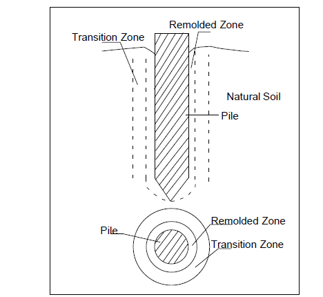
Figure 2. Remolded zone and transition zone due to pile driving. (Chen et al.)
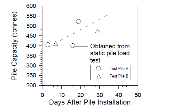
Figure 3. The relationship between pile capacities and the time lag after pile installation are in marine soft clay. (Chen et al.)
Other research projects have focused on seismic projects for bridges in California in order to have well-documented filed tests that evaluated the pile installations in clay for safety and cost concerns. In a project conducted by Pestana (et al., 2002), a pile was driven into marine clay and a high pore pressure was noted and decreased with increasing distance from the pile/soil interface. The pore pressures were noted to dissipate with time and 80% consolidation of the soils was indicated. The results of this experiment provided information in regard to material properties and soil for use in areas of seismic activity. For these types of areas, ideal conditions have been proposed to show the conditions of the soil and the corresponding pore pressures and stress for sites containing clay type soil. (Figure 4)
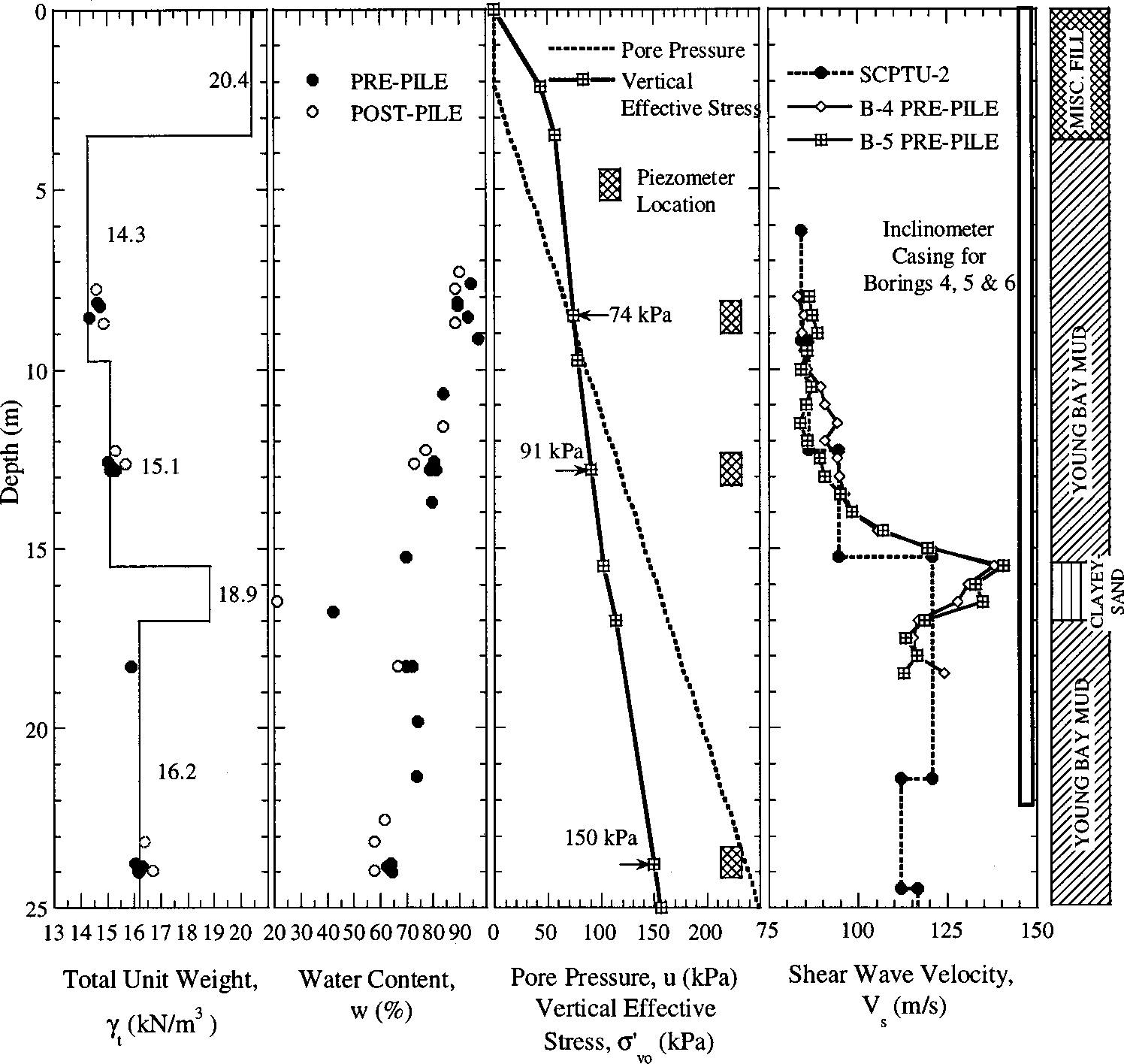
Figure 4. Ideal soil profile illustrating pore pressure and stress. (Hunt et al., 2002)
In a more recent research paper written by Gavin (2011), the author investigates the evolution of design for estimating the resistance of piles. In this paper the total stress approach is evaluated, as well as other stress methods and cavity expansion methods. The author indicates that the total stress method still remains as the most used approach in measuring capacity of the piles in clay. However, the author indicates that the basic from of this method should be used which links the average shaft resistance to the average undrained strength of clay along a pile shaft. This basic method uses an adhesion factor. Although Carter (et al., 1979) brought great advances with the stress method during the 1970’s the total stress design was modified in the 1980s. Studies conducted by Kraft et al (1981) and Morrison (1984) evaluated the poor reliability of total stress design. Then in 1985, Randolph and Murphy found that the poor reliability of the total stress design could be structured more reliable if considering the undrained strength ratio.
Gavin (2011) also describes methods that link the shaft resistance to the stress tests such as the Cone Penetration Test (CPT). Gavin (2011) indicates that the CPT test is used for this purpose and has a few benefits to include: the procedure for the installation of the cone is similar to pile penetration, the high logging rate of the cone resistance and pore pressure results in data for stratigraphic changes and the CPT method is not dependent on an operator.
The paper by Gavin (2011) describes a research project presented by Coop and Wroth (1989) in which pile were examined in over-consolidated clay. Coop and Worth’s (1989) results illustrated a 10 minute time lag for the transducer to obtain the specific depth. From these results, Randolph (2003) disputed that it was pore pressure dissipation that was responsible for the time lag. A graph comparing measurements of porewater pressure during the installation of piles into lightly over-consolidated silty clay and in heavily over consolidated clay was provided in the research paper and is illustrated in Figure 5. The data collected from both piles was included from sensors on the pile shaft and piezometer that were placed in the soil at the same distances in both the lightly and heavily over-consolidated clay. The results illustrated that at both the light and heavy clay, the maximum change in “u” was found at the pile tip, which was close to the sensor and that the increase in porewater pressure was significantly greater in the lighter soil.
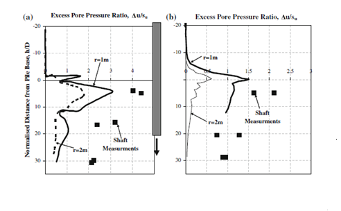
Figure 5. Normalized Excess Pore Pressures measured in light soil (a) and heavy soil (b) Gavin (2011)
Gavin (2011) also discusses previous research conducted in 2010, (Gavin et al., 2010). In this project, there were multiple field studies conducted to investigate the effect of the installation method on shaft resistance of pile in soft silty clay. The results from this study indicated that the radial total stress and pore water pressure were directly affected by the installation method. In fact, the radial total stress and pore water pressure both increased during the installation process, with the dominant problem being the high pore pressures that were developed during the installation of the pile into the soft silty clay. In addition, there was also a finding that illustrated that the stresses that were measured after the dissipation of the porewater pressure was not affected the installation process and that all piles had the same shaft resistance during the testing. This indicates that further testing should be conducted since the results were not in correlation with the predicted hypothesis since other studies have shown that pile resistance, total stress and pore pressure at the shaft were significantly altered during pile installation (Doherty and Gavin, 2010).
The previous two research literature reviews have focused on research that supported the total stress methods for piles driven in clay. The total stress method is the more widely used method; however, there is some research that is more directed towards a fundamental stress approach, instead of the cavity expansion method, for example. Therefore, in the paper presented by Marchetti (et al., 1986), the focus was on the fundamental stress approach. The authors use this approach based on previous findings such as when the pile is driven in clay, the high pore pressure are found increased at the pile-clay interface with a decrease in stress (Figure 6). In addition, as the reconsolidation occurs at the interface, the stress rebuilds again and the total pressure decreases. The purpose of creating a fundamental approach to predict the skin friction from pile driven in clay and to determine this prediction for field use as it is a necessary step. The methods for this project entailed two different test piles that were driven to depths of 21.6 m and 27m for 79 and 86 days, respectively. The results of the project indicated that pore pressure does increase at the pile-clay interface and offers a possible method for evaluating skin friction, which is directly influenced by pore pressure. (Marchetti et al., 1986)
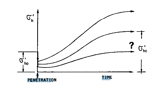
Figure 6. Schematic Diagram illustrating the variation of Horization Effective Stress, Interface caused by the Pile Installation. (Marchetti et al., 1986)
Swan from the University of Iowa indicates that excess porewater pressure dissipates extremely fast in saturated cohesionless soil and can therefore regain its strength extremely rapidly as well. However, it is also indicated that if the soil is not saturated, there will be no porewater pressure during the driving of the piles. This results in the lack of the regaining of the soil strength or “freeze”. In addition, during the driving process, the surrounding soil experiences a highly compressive stress, which in turn results in a buildup of lateral stress. This can be caused when piles are driven into soils with high density, such as clay (Figure 7). During driving of high-displacement piles, adjacent soils will experience high compressive stresses, causing a buildup of large lateral effective stresses. As seen in Figure 7, this occurs when a pile is driven into a high displacement soil with a high density. The soil experiences shearing and then results in an expansion which in, turn generates a high lateral stress between the pile and soil. Over time the stress may subside; however, during the initial period of time the soil is not capable of being driven into due to the high skin friction capacity. (Swan)
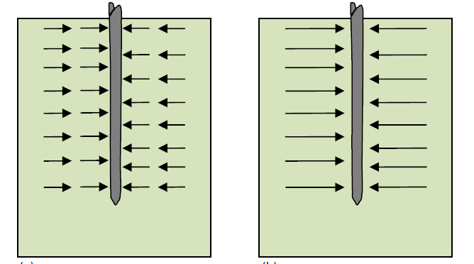
Figure 7. a) Illustrates a high displacement pile driven into a dense cohesionless soil. Results in lateral stress between pile and soil. b) Illustrates lateral stress caused by the high displacement pile. (Swan)
In a report conducted by the U.S. Department of Transportation, Federal Highway Administration, in 2000 (Paikowsky and Hart), a model pile was created. The model pile is known as the Multiple Deployment Model Pile (MDMP). It is a tool that is calibrated that is used to monitor the interaction between the pile/soil over the course of the pile history. The model pile is able to monitor the pile installation, the pore pressure and the behavior of the pile. The model pile simulates the field conditions. The data obtained from the simulation is used to therefore calculate the pore pressure dissipation time and predict the soils response to the predicted conditions. In addition, the MDMP can monitor the pile/soil interaction the entire life cycle of the pile. Furthermore, the MDMP is able to accurately obtain the pile capacity can, or “freeze”. The MDMP was initially deployed two times during 1996. The deployment was successful and resulted in the evaluation of the pile capacity gain, the excess pore water pressure dissipation, and the radial stresses.
An important aspect of the MDMP is the design and ability to obtain the pore pressure increase due to the dissipation of the excess pore pressure. From this model, the data is able to be analyzed and the rate of the pore pressure dissipation can be determined and used to estimate the amount of time that is required for the excess pore pressure to dissipate. The data is plotted on a semi-log plot and the best fit line from the 20% to 80% dissipation is illustrated on the linear part of the curve, as seen in Figure 8.
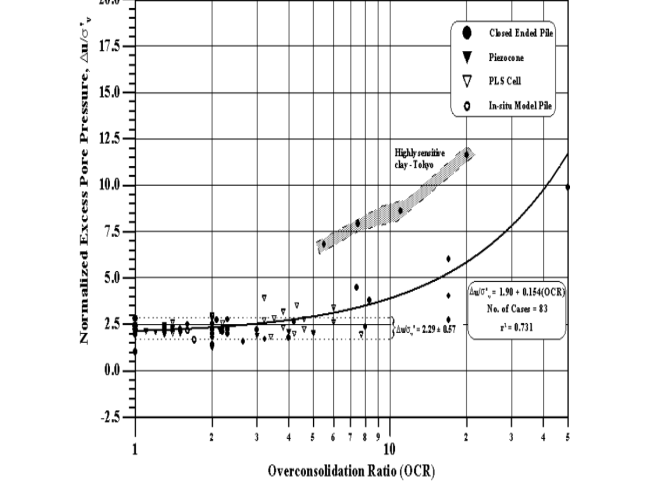
Figure 8. Illustrates results obtained from MDMP, model pile. (Paikowsky and Hart, 2000).
Summary
Pore pressure buildup and dissipation is a factor that affects piles driven in clay. Pore pressure buildup can cause instability and although the pore pressure will dissipate over time, it is dependent on the permeability and compressibility factors of the soil itself. Research has focused on this topic of pile driven in clays for decades. In 1979, Carter et al., brought information that was imperative to research piles driven in clays. Carter focused on the stress factors that occurred in the soils after the piles were driven in clay. In addition, the researchers created formulas to predict and calculate total stress for piles. Furthermore, it allowed the researchers to develop calculations to incorporate the expansion of the cavity, as well as total pressure and pore pressure.
Chen (et al.) conducted a field research project to illustrate the effect of time on pile capacity when driven in clay and found that choosing the type of soil is imperative to the strength of the reconsolidation, as well as the cost of the project, due to the decreased number of pile required if using soil that creates a higher capacity, such as clay. As seen in Table 1, as time increases, so does the pile capacity. This type of information is essential for areas such as California, where there are numerous projects underway for seismic foundations. Results from studies, therefore, point to using clay as the type of soil for pile driving. Further indication is supported from the research conducted by Gavin (2011), as the methods used by Carter and other research engineers in the 1970s and 1980s were evaluated in his paper to support his research ideas. Gavin (2011) indicated the Cone Penetration Test or CPT test was beneficial in order to determine pore pressure results. In addition, from Gavin’s research (2011), results showed that the total stress and pore water pressure were directly affected by the installation procedure and illustrated the increase in total stress and pore water pressure during installation into soft silty clay.
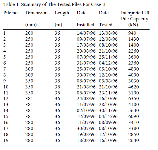
Table 1. Pile capacity from the pile load test together from tested piles. Increasing pile capacity with time. (Hunt et al., 2002)
The paper published in 2000 on the development and field testing of Multiple Deployment Model Pile (MDMP) seemed to take all of the information that has been researched by engineers over the decades and apply the principles and develop field methods in which the piles could be tested on-site and for long periods of time. The engineers used the model and find the rate of pore pressure dissipation, capacity gain, skin friction, and total stress. The results of their study were successful during installation, and were capable of monitoring the pile capacity gain against time along with the pore pressure and stress changes. The researchers concluded that the MDMP provided a direct measurement of the soil and pile interaction. The accuracy of the results is still not fully understood, as with other research in this field.
Conclusion
Overall, the researchers continue to study piles driven in clay that factors that affect the piles, such as pore pressure buildup and dissipation. Researchers have been successful in their calculations and filed methods; however, further investigation is required in order to determine the accuracy of the results for each method and and study described. The study conducted by the U.S. Department of Transportation (Paikowsky and Hart, 2000), however, seems to have reliable data since the MDMP was an actual device that could be placed into the soil. In addition, the MDMP had multiple sensors that are capable of retrieving the pore pressure and total pressure, as well as radial stresses. Therefore, further research should be conducted in order to continue with the development of the MDMP and apply these methods to areas with seismic activity in order to determine the most effective soil for pore pressure buildup and dissipation, as well as the cost benefits to such projects in using clay.
References
Abebe, a. And smith, i.g. ph.d. Pile foundation design: a student guide. School of the built environment, napier university, edinburgh.
Carter, j.p., randolph, m.f.. Wroth, c.p. (1979). Stress and pore pressure changes in clay during and after the expansion of a cylindrical cavity. International journal for numerical and analytical methods in geomechanics. 3(30):305-322.
Chen, c.s., liew, s.s., tan, y.c. time effects on the bearing capacity of driven piles. Ssp geotechnics sdn bhd, malaysia.
Hunt, c., pestana, j.m., bray, j.d. (2002). Effect of pile driving on static and dynamic properties of soft clay. Journal of geotechnical and geoenvironmental engineering. Pp. 13-24.
Gavin, p.d.k. (2011). The shaft capacity of displacement piles in clay: a state of the art review. Geotech geol eng . Spinger science + business media b.v. 2011
Gavin k, gallagher d, doherty p, mccabe b (2010) field investigation assessing the effect of installation method on the shaft resistance of piles in clay. Can geotech j 47(7):730–741.
Komurka, v.e, and wagner, a.b. (2003). Estimating soil/pile set-up. Wagner komurka geotechnical group, inc. Whrp 03-05. 58pp.
Kraft lm, focht ja, amerasinghe sf (1981) friction capacity of piles driven into clay. J geotech eng div 107: 1521–1541.
Morrison mj (1984) in situ measurements on a model pile in clay. Phd thesis, massachusetts institute of technology.
Marchetti, s., totani, g., campanella, r.g., robertson, p.k., taddei, b. (1986). The dmt-obc method for piles driven in clay. Reprinted from proceedings of in situ. Gt div., axe. Pp765-768.
Paikowsky, s.g. and hart, l.j. (2000). Development and field testing of multiple deployment model pile (mdmp). U.s. department of transportation. Federal highway administration. Publication number: fhwa-rd-99-194. 284pp.
Pestana, j., hunt, c., bray, j. Soil deformation and excess pore pressure field around a closed-ended pile. Asce. 128(1):1090-0241.
Swan, c.c. changes in soil during pile driving. Foundation engineering. The university of iowa. Web. Retrieved from: http://www.engineering.uiowa.edu/~swan/courses/53139/notes/changes-in-soil-during-pile-driving.pdf.
Wsdot. (2010). Wsdot geotechnical design manual m 46-03.01 pp.51.

Time is precious
don’t waste it!

Plagiarism-free
guarantee

Privacy
guarantee

Secure
checkout

Money back
guarantee


